Ebyte E104-BT53A3 Rf Modül
| Parameters | Value |
Specification |
| Reference distance |
120m |
Clear and open, antenna gain 5dBi, antenna height 2.5m,air rate 1kbps |
| Crystal frequency |
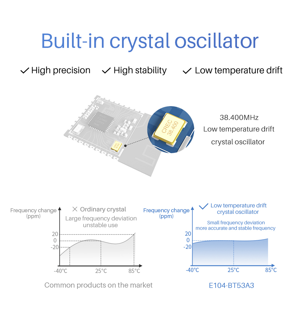
38.4MHz |
- |
| supporting agreement |
BLE 5.2 |
- |
| Packaging method |
SMD |
- |
| IC full name |
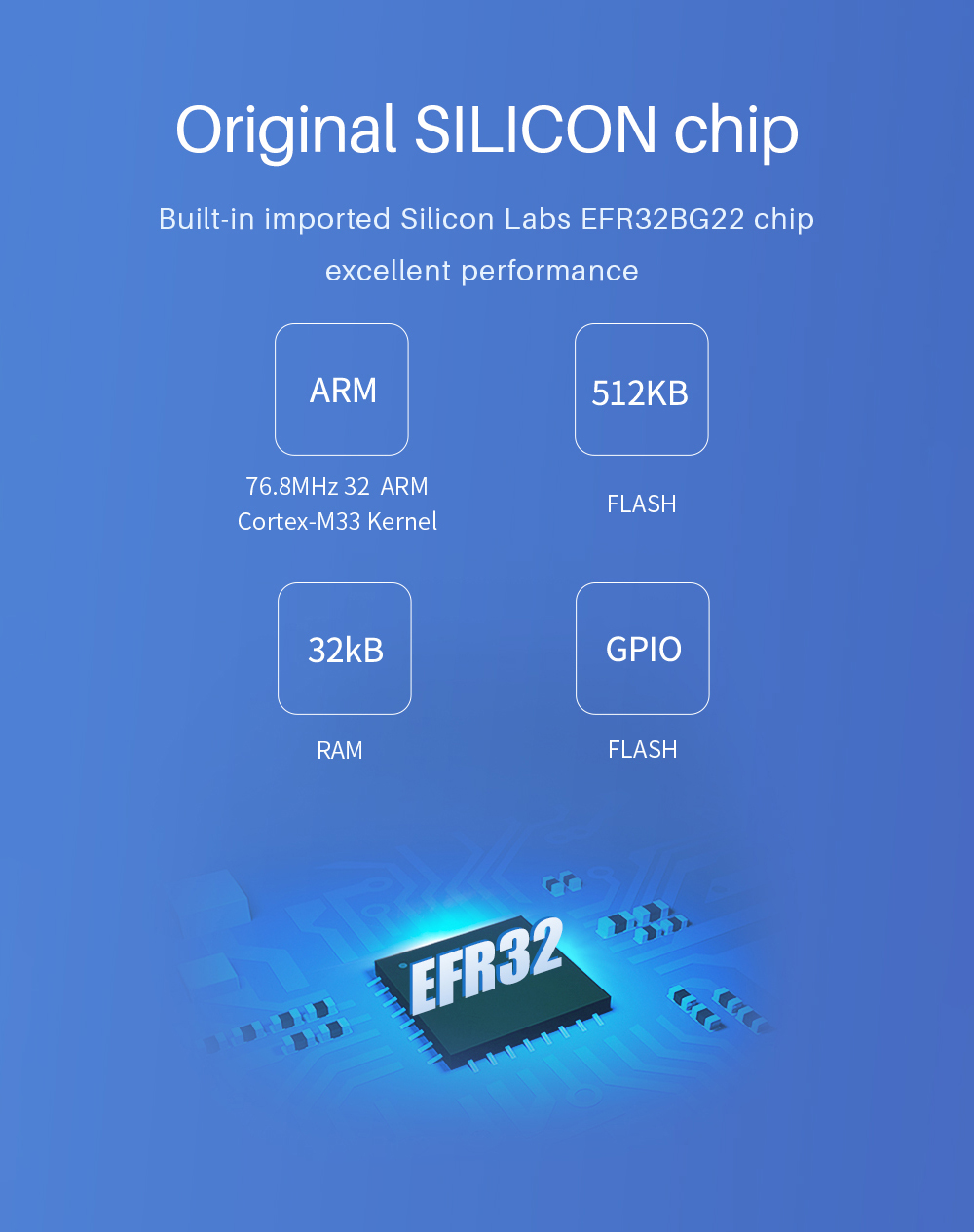
EFR32BG22C224F512GM32 |
- |
| FLASH |
512KB |
- |
| RAM |
32KB |
- |
| Kernel |
ARM®Cortex®-M33 |
- |
| Dimensions |
13*19mm |
- |
| RF interface |
PCB |
Equivalent impedance is about 50Ω |
| Parameters | Min. | Typ. | Max. | Unit | Specification |
| Working voltage |
1.9 | 3.3 | 3.6 | V | ≥3.3V can guarantee the output power |
| Communication level | - | 3.3 | - | V | Using 5V level has the risk of burning |
| TRX | - | 7.5 | - | mA | @Transmit power 6dBm |
| RX | - | 3.6 | - | mA |
- |
| Sleeping Current |
- | 0.17 |
- | uA |
Software is off |
| Working frequency band |
2402 |
2440 |
2480 |
MHz |
Support ISM frequency band |
| Working temperature |
-40 | - | +85 | ℃ | Industrial design |
| Max TRX Power |
- | 6 | - | dBm |
- |
| Receiving sensitivity |
- | -106.7 |
- | dBm |
-106dbm sensitivity @125kbps GFSK; -98.9dbm sensitivity @1Mbit/s GFSK; -96.2dbm sensitivity @2Mbit/s GFSK; |
| Air Rate(GFSK) |
125k |
- | 2M |
bps |
Programmable by User |

| NO. |
Name | Type | Definition |
| 1 | GND |
Input |
Ground wire, connect to power reference ground |
| 2 | PB02 |
Input/Output |
MCU GPIO (see EFR32BG22 manual for details) |
| 3 | PB01 |
Input/Output |
MCU GPIO (see EFR32BG22 manual for details) |
| 4 | PB00 |
Input/Output |
MCU GPIO (see EFR32BG22 manual for details) |
| 5 | PA00 |
Input/Output |
MCU GPIO (see EFR32BG22 manual for details) |
| 6 | PA01 |
Input |
SWCLK, serial line debugging clock input debugging and programming (see EFR32BG22 manual for details) |
| 7 | PA02 |
Input |
SWDIO, serial line debugging and programming debugging (see EFR32BG22 manual for details) |
| 8 | PA03 |
Input/Output |
MCU GPIO (see EFR32BG22 manual for details) |
| 9 | GND |
Input |
Ground wire, connect to power reference ground |
| 10 | GND |
Input |
Ground wire, connect to power reference ground |
| 11 | PA04 |
Input/Output |
MCU GPIO (see EFR32BG22 manual for details) |
| 12 | PA05 |
Input/Output |
MCU GPIO (see EFR32BG22 manual for details) |
| 13 | PA06 |
Input/Output |
MCU GPIO (see EFR32BG22 manual for details) |
| 14 | VCC |
Input |
Power supply, range 1.9 ~ 3.6V (recommended to add ceramic filter capacitors externally) |
| 15 | VCC |
Input |
Power supply, range 1.9 ~ 3.6V (recommended to add ceramic filter capacitors externally) |
| 16 | GND |
Input |
Ground wire, connect to power reference ground |
| 17 | GND |
Input |
Ground wire, connect to power reference ground |
| 18 | PD01 |
Input/Output |
MCU GPIO (see EFR32BG22 manual for details) |
| 19 | PD00 |
Input/Output |
MCU GPIO (see EFR32BG22 manual for details) |
| 20 | PC00 |
Input/Output |
MCU GPIO (see EFR32BG22 manual for details) |
| 21 | PC01 |
Input/Output |
MCU GPIO (see EFR32BG22 manual for details) |
| 22 | PC02 |
Input/Output |
MCU GPIO (see EFR32BG22 manual for details) |
| 23 | PC03 |
Input/Output |
MCU GPIO (see EFR32BG22 manual for details) |
| 24 | PC04 |
Input/Output |
MCU GPIO (see EFR32BG22 manual for details) |
| 25 | PC05 |
Input/Output |
MCU GPIO (see EFR32BG22 manual for details) |
| 26 | RST |
Input |
Chip reset trigger input pin, effective when low level |
