EBYTE 4G DTU LTE MODEM E840-DTU(4G-02E)

| Parameter | Description |
| Frequency |
LTE-FDD:B1/B3/B7/B8/B20/B28A WCDMA:B1/B8 GSM:B3/B8 |
| LTE characteristic |
Support max. of 3GPP R8 non-CA Cat 4 FDD and TDD Support 1.4MHz~20MHz , Downstream support: MIMO LTE-FDD: Max downstream rate 150Mbps, Max upstream rate50Mbps |
| WCDMA characteristic | WCDMA: Max downstream rate 384Kbps, Max upstream rate 384Kbps |
| GSM characteristic |
GPRS: Max downstream rate 107Kbps,Max upstream rate 85.6Kbps EDGE: Max downstream rate 296Kbps,Max upstream rate 236.8Kbps |
| Network protocolcharacteristic |
TCP/UDP/MQTT |
| Hardware Characteristic | Description |
| Antenna |
SMA |
| Data interface |
RS485 / RS232 |
| Baud rate |
Max 921600bps,default 115200bps |
| Transmittingpower |
Class 4 (33dBm±2dB) for GSM900 FDD B3: -101.5dBm (10M) |
| Consumption(Typical) |
11uA @ power off |
| Bandwidth |
1.4/3/5/10/15/20MHz |
| Operating temperature | -30℃- +70℃ extending to -40℃~+85℃ |
| Operating voltage |
DC 8V~28V |
| Size |
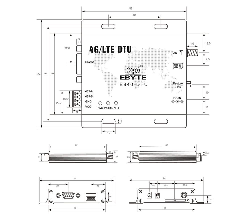
82×84×24mm |
| RS485 /RS232 |
RS485/RS232 |

| Pin No. |
Name | Description |
| 1 | RS232 |
RS232 interface |
| 2 | 485_A |
To connect the end A of other RS485 device |
| 3 | 485_B |
To connect the end B of other RS485 device |
| 4 | GND |
Ground |
| 5 | VCC |
Power supply, 8~28V,12V or 24V is recommended |
| 6 | PWR |
Power indicator |
| 7 | WORK |
Blue: Receipt transceiver pin, when the network receives data or the serial port receives data (50ms high/10ms low) Green: device status indication pin, Low: The device is powered on to search for a SIM card 1800ms low, 200ms high: The device checks the correct SIM card and is attaching to the network; High: The device is attached to the network successfully; |
| 8 | NET |
Green: Socket A link connection status indication pin High: Socket A is successfully connected to the network server; Low: Socket A is not successfully connected to the network server; Blue: Socket B link connection status indication pin High: Socket B is successfullyconnected to the network server; Low: Socket B is not successfully connected to the network server; |
| 9 | DC-IN |
DC adaptor,8~28V, 12V or 24V is recommended |
| 10 | RST |
Dip switch(downward,reset) |
| 11 | Restore |
Dip switchAfter the radio is powered on normally, the Restore dials from top to bottom, and continues down for 3~10S, then from bottom to top. After the process is completed normally, the radio parameters will be restored to the factory settings and restartedimmediately. |
| 12 | SIM |
SIMSIM card slot |
| 13 | ANT |
Antenna (SMA-K,50Ω impedance) |


